What is Peak-To-Average Power Ratio: OFDM
What is Peak-To-Average Power Ratio? One of the major drawbacks for OFDM devices is the weak performance of an amplifier. There are two primary reasons for this. The first one is due to the usage of QAM modulation. This requires using a linear power amplifier to meet ACLR (Adjacent channel leakage ratio) requirements for performance. This is true in any system employing QAM modulation. Take UMTS as an example however, in OFDM systems, this is further complicated by another factor that is related to the nature of multi-carrier the OFDM signal.
What is Peak-To-Average Power Ratio: OFDM
It is the OFDM signal is made up of multiple sinusoids with different frequencies and carrying various modulation symbols. The sum of these sinusoids creates a complex waveform that has a much higher peak-to-average ratio than one single carrier signal could have. Since diverse types of transmission symbols happen on the multiple subcarriers simultaneously the combined transmitted signal displays the regular appearance of an extremely higher level of PAPR (Peak to Average Power Ratio). The greater the number of subcarriers, the more frequently this happens. This means that in order to keep the linear operation within the power amplifier, a greater power backup-off has to be in place. This can mean lower efficiency or costlier power amplifiers.
There are many methods that can be used within OFDM systems to reduce the issues of high PAPR. The majority of them relate to the design of power amplifiers as well as signal conditioning. These methods are employed for the LTE downlink that is completely OFDMA system. However, the cost, as well as power efficiency, are extremely important for the UE as a result, which is why 3GPP has decided to utilize the modification of OFDMA for the uplink. This is known in the SC-FDMA (Single Carrier Frequency Division Multiple Access). This method assigns the transmitted signal a single characteristic of the carrier that in turn decreases the PAPR.
SC-FDMA Principles of Operation. ( sc-fdma block diagram )
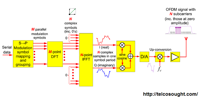
sc-fdma block diagram The layout typical of an SC-FDMA receiver is illustrated in the diagram. In spite of its name, the radio signals for the SC-FDMA are orthogonal multiple carrier signals like OFDMA. The term “single carrier” is a reference to the preprocessing of the baseband information prior to its transfer to the IFFT.
Data streams are delivered in a series in the process of radio transmission. The first step is the modulation symbol mapping that produces multiple blocks of “M” complicated valued symbols. The amount of bits that are represented by each of the modulation symbols is determined by the modulation scheme used.
Each set of “M” modulation symbols is then scanned by an M-point DFT which generates an output that effectively represents the frequency components of the particular group of symbols for modulation. The frequencies that are mapped to the inputs allocated by the N-point IFFT which is the number of subcarriers in the. The diagram illustrates the local mapping, however, a distributed mapping to subcarriers that are allocated is also feasible.
Its output from the IFFT and modulator will be a multi-carrier signal. But unlike OFDMA there isn’t a direct mapping of every baseband symbol to individual subcarriers that are transmitted. Instead, frequencies of every baseband symbol are represented across all subcarriers that are transmitted This makes the transmitted signal have the characteristic of a single carrier. This produces a signal with a better PAPR when compared to an identical OFDMA transmission.
Also Read:-
- Radio Carrier Orthogonality- Ofdm Principles
- OFDM Resilience meaning to Time Dispersion & Multipath Fading
- Concept Components for OFDM wifi
- OFDM transmitter and receiver block diagram explanation
- Cyclic Prefix In OFDM
- OFDM Subcarrier Assignment
- Discussion on 802.11ax & “Wi-Fi Re-defined” with Nitin Madan, PLM, Broadcom
- OFDM Subchannelization Organization
- OFDM Channel Adaptation.
- OFDMA Allocation to Users
- Turbo Coding for Error Correction