LTE Evolved Packet Core and S1 Interface
Hi in this 4G/5G Ran topic we share the LTE Evolved Packet Core and S1 Interface. The Evolved Packet core reduces the complexity in the RAN is mirrored by a similar reduction in the core network. Where the EPC structure consists of five main nodes, If others may be required for backward-compatibility purposes.
The backhaul links to the core network to be carried by the S1 interface. And The general structure of the Iub interface which replaces the traffic over S1 is logically split into two Faces.
So Let’ learn more on the topic:-
The EPC Evolved Packet Core:-
The EPC reduced diversity in the RAN is imaged as a similar reduction in the core network where Evolved Packet Core structure consists of the five main nodes if others may be required for backward compatibility purposes.
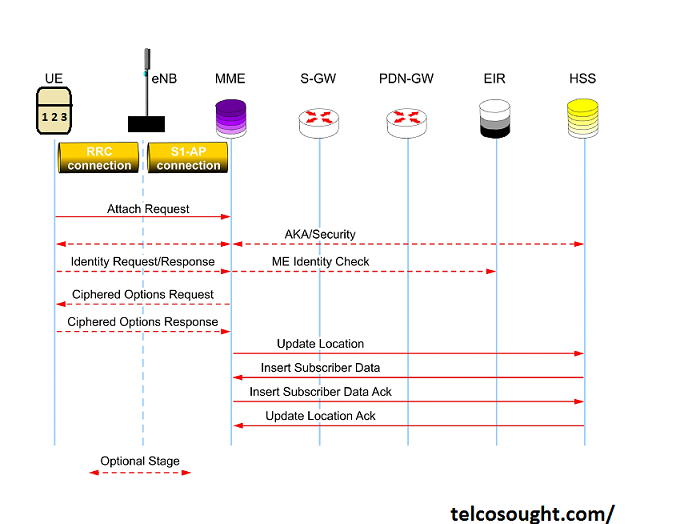
The MME handles control plane functions associated with mobility management authentication and idle mode handling location updates and paging. In which sense it is appreciably analogous to the Visitor Location Register(VLR ) or GPRS Mobility Management(GMM) functions found in legacy networks. The MME is also beholden for EPC bearer control so that it handles connection signaling control.
The Serving Gateway (S-GW) and Packet Data Network Gateway (PDN-GW ) are appreciably analogous to the Serving GPRS Support Node (SGSN) and Gateway GPRS Support Node (GGSN ). And we found in R99 networks and perform user plane handling and switching the interfacing functions. alternate legacy systems, anyhow, bearer control has been removed from these devices and resides with the MME.
The Policy and Charging Rules Function (PCRF) is an optional network element. If deployed, it handles QoS and bearer policy bring about and also provides charging and rating facilities. If a PCRF is not deployed then some of its functions can alternately be performed by the PDN-GW.
Subscriber management and security functions are handled by the Home Subscriber Server (HSS). Which acculturates the functions of the legacy Home Location Register (HLR). And which is already familiar from R5 elements such as the IP Multimedia Subsystem (IMS ).
For backward collaboration purposes, SGSNs has deployed to legacy parts of an operator’s network can be collaborated to both the MME for mobility management and S-GW for user plane flows.
The MME then provides legacy systems with an interface to the HSS, and the S-GW and PDN-GW assume the role before long performed by the GGSN.
The packet data services of legacy (GSM/GPRS, R99, and HSPA) networks and LTE/SAE systems can in consequence interwork via a unified set of core network elements if required.
LTE S1 Interface:-

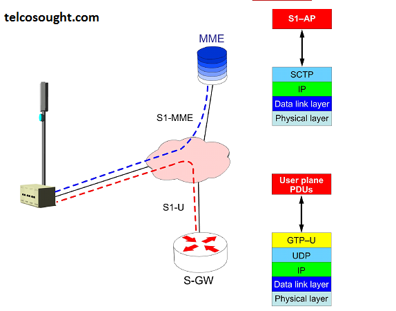
The LTE backhand links to the core network are carried by the S1 interface. The general structure of the Iub interface which replaces the traffic over the S1 is logically split into two faces.
The Interface S1-U flows carry user plane traffic and S1-MME flows carry mobility management, carrier control, and direct transfer control plane traffic.
Message structures for the S1-MME that operate between the eNB and the MME are defined by S1 Application Protocol (S1AP). The S1AP performs capitations that can be seen as a combination of those performed by the R99 Radio Access Network Application Part (RANAP) and the GPRS Tunnelling Protocol – Control plane (GTP-C).
To provide additional redundancy, traffic separation, and load balancing. The S1-flex concept allows each eNB to maintain logical connections to the multiple S-GWs and MMEs. There may accordingly be multiple instances of the S1 interface per node.
The S1-U interface employs GTP-U to create and manage user-plane data and contexts between eNB and S-GW.


