Concept Components for OFDM wifi
OFDM wifi is a clear benefit as a modulation method for radio systems with wideband frequencies. Knowing the ways in which OFDM can be used to work in the real world requires first getting a fundamental understanding of three fundamental concepts:
OFDM is made possible by the combination of these three essential concept elements.
Defining Orthogonality ( OFDM wifi )
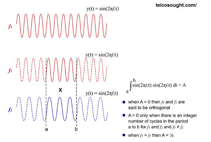
The term “orthogonal,” taken in Greek for the right angle, is a term that has a distinct meaning when it is applied to waveforms. The two sine waveforms are classified as orthogonal if the integral value of their products is zero. This is mathematically expressed by the figure.
The prerequisite for orthogonality is that two sine waves share the same number of cycles in the integration time and they do not have an identical frequency. When one sine wave is not a numeric number of cycles during the period of integration, then the result of integration is not zero, and consequently, they’re not orthogonal. The requirement for orthogonality is crucial for the successful separation and then independent demodulation of OFDM subcarriers.
A unique case happens in the case that the sine waves are identical in frequency. In this situation, it is orthogonal if they’re not in phase at 90deg, i.e. sine and cosine will always be orthogonal.
Principles of QAM ( OFDM wifi )
All OFDM systems employ a certain form or QAM (Quadrature Amplitude Modulation). Be aware of this: QPSK is a particular type of QAM with only four phase states and an amplified state.
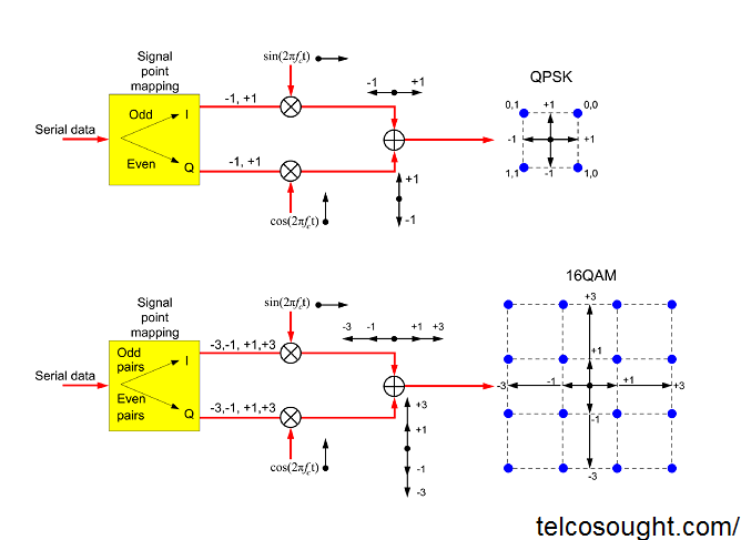
The diagram depicts a fundamental QPSK modulation train. The serial input data is divided into two concurrent (I or the Q) streams. In this case, the number 1 logic bit has been assigned to a symbol that has value -1 while a zero bit is assigned to a symbol that has value +. A single symbol at each time is multiplied on the respective I and Q version of the carrier radio. Both the I and Q messages are combined to form the QPSK signal as well as a four-point constellation.
The only change needed to allow the same train of modulation to generate a higher-quality QAM signal lies in the mapping of symbols. To create the 16QAM signal, two bits are now assigned to each of the Q and I streams within each symbol. So, four bits total are input in each symbol period. three and the initial bits are integrated to stream I whereas the fourth and second are mapped to the Q stream. The following rule for mapping symbols is then implemented in both of the Q and I streams:
Map 01 to +3
Maps 00 to +
10 maps up to -1
11 maps from 3
The remainder of the train for modulation stays the same. The symbols are then multiplied on the different versions of the carrier. The signal I, as well as Q, are combined to create a 16QAM signal as a 16-point constellation. Be aware that, as the result of this new constellation, it will have a higher average power. To stop this from happening, the signal will be multiplied with the suitable scaling coefficient.
Demodulation
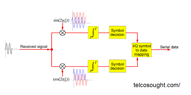
The signal received is split into its Q and I components by multiplying it with the identical signal I as well as Q that is used for the modulator. This results in when you look at the I side,, the cosine component will be integrated into zero. In contrast, for branch Q its sine component is expected to be integrated to zero.
The result of the integration for each branch is of a specific magnitude based on the Q and I symbol mapping. In essence, this is amplitude demodulation. A threshold detector can then be employed to retrieve these I or Q symbols. Then, a symbol-to-bit mapping process is utilized to recreate the digital data stream.
Related Topic:-