OFDM transmitter and receiver block diagram explanation
Hi In this article we learn about the OFDM transmitter and receiver block diagram explanation. which combines the elements of symbol mapping and QAM with the application of IFFT to produce an OFDM signal.
The OFDM signal is then down-converted and sampled for analog/digital conversion. To include the cyclic prefix, the sampling rate will be factored in at this point. You can learn the 5G Tutorial.
The OFDM Transmitter
This diagram shows a block diagram of the transmitter, which combines the elements of symbol mapping and QAM with the application of IFFT to produce an OFDM signal.
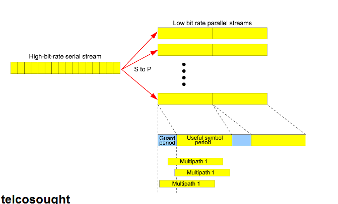
First, the serial data that will be carried over the radio link must go through a serial to the parallel conversion process. The number of data-carrying Subcarriers in the system will determine the number of parallel streams. Because the IFFT offers the best efficiency, this number will almost always be a power to two.
The bits on parallel data streams will be grouped according to the symbol constellation of the M-ary QAM scheme. For QPSK bits, they are divided into pairs. 16QAM bits are divided into fours while 64QAM bits are split into sixes.
Next, symbol point mapping is used to map the bit groups of each parallel data stream. These complex numbers symbols are then used to input an N-point IFT. N is a power of 2 equivalent to the number of subcarriers.
The output of the IFFT is a series complex number of digital samples that represent the OFDM signal for each symbol period. The cyclic prefix can be added at this point by copying the last sample onto the beginning symbol period. These complex real and imagined sample values are used for the formation of the I and Q symbol streams. The I and Q branches then get multiplied to create sine and cosine representations for the radio carrier. This creates a digital representation the multicarrier required M-ary QAM modulated transmit signals.
The digital-to-analog conversion can convert the signal to the channel center frequency required before it is amplified and transmitted.
The OFDM Receiver
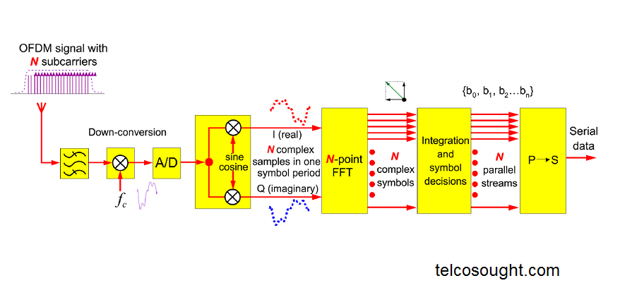
The OFDM signal is then down-converted and sampled for analog/digital conversion. To include the cyclic prefix, the sampling rate will be factored in at this point.
The cyclic prefix of the sampled signal has been removed and it is divided into I and Q components. This results in a series of complex samples that can be used as inputs to the FFT.
FFT is a method of reducing the complex waveforms in the symbol period to N complex value. Each represents a modulation symbol on one subcarrier. To recover the bits that are represented by each M-ary modulation symbol, M-ary demodulation is done by reverse symbol mapping and integration.
Finally, parallel to serial conversion rebuild the original serial bitstream.
Related Post: