orthogonal frequency division multiplexing ( OFDM PRINCIPLES )
orthogonal frequency division multiplexing ( OFDM PRINCIPLES ). Orthogonal frequency-division Multiplexing is a technique of data transmission in which an information stream is divided into various narrowband subchannels with closely spaced frequencies rather than a single wideband channel frequency. It is typically used for wireless data transmission, but it can be used in wired and fiber optical communication too.
In a standard single-channel modulation system every data bit is delivered sequentially or one after the other. In OFDM it is possible for several bits to be transmitted simultaneously, or simultaneously and in distinct parts of channels. This allows each substream’s information rate to be smaller than could be needed for a single stream with similar bandwidth. This means that the system is less prone to interference and provides better data bandwidth.
Table of Contents
orthogonal frequency division multiplexing ( OFDM PRINCIPLES )
CONTENTS
- Radio Carrier Orthogonality
- Spectral Efficiency of OFDM
- The Resilience of Time Dispersion
- Resilience Multipath Fading
- Concept Components to OFDM
- Definition of Orthogonality
- The fundamentals of QAM
- Demodulation
- The Fourier Transform
- The Transmitter OFDM
- It is the OFDM Receiver
- The Cyclic Prefix
- Subcarrier Assignment
- Scalability is a key feature of OFDM
- Scalable OFDM
- OFDMA Strategies for Resource Allocation
- Subchannelization Organization
- Channel Adaptation
- OFDMA Allocation to Users
- Turbo Coding of Error Correction for
- Turbo Decoding
- OFDM P/A Power Ratio
- SC-FDMA Principles of Operation
- MIMO Concept
Radio Carrier Orthogonality
Think about a radio transmitter being modulated with 10 kbit/s bit-stream with QPSK (Quadrature Phase Shift Keying). You could observe a spectral envelope as a result of a (sin x)(sin x) / x function as illustrated in the diagram. The first null is located 5 kHz away from the center frequency.
Spectral Efficiency in OFDM
When we consider the two interlocking two QPSK radio carrier carriers it is observed it has a high spectral efficiency. If the actual bandwidth of the transmitting signal is thought to be the frequency separation between the nulls that are first, then the single QPSK carrier modulated at 10 kbit/s would result in the null-to-null bandwidth in the range of 10 KHz.
Resilience to Time Dispersion ( OFDM ).
The efficiency of the spectrum isn’t the only benefit of the use of OFDM. It also shows high resistance to Multipath effects inside the channel. This includes blurring and dispersion of time.
Since the data rate of individual subcarriers of the channel is extremely small, the symbol time is also lengthy. The resultant symbol period tends to be much longer than the time dispersion which occurs within the channel. This means that a relatively easy equalization can be employed to reduce multipath, even though the net rate for the entire channel is extremely high.
Resilience meaning to Multipath Fading.
The tolerance for multipath-related fading stems from the broadband characteristics of the channel. A narrowband channel is likely to have flat fading characteristics, which means that the fading patterns are consistent across the entire bandwidth of the channel. The results of this can be observed in the figure.
OFDM channels, on contrary, is typically used to carry extremely high data rates, which is why they require a number of subcarriers that have an extremely large bandwidth.
Concept Components for OFDM
OFDM wifi is a clear benefit as a modulation method for radio systems with wideband frequencies. Knowing the ways in which OFDM can be used to work in the real world requires first getting a fundamental understanding of three fundamental concepts:
OFDM is made possible by the combination of these three essential concept elements.
Defining Orthogonality ( OFDM )
The term “orthogonal,” taken in Greek for the right angle, is a term that has a distinct meaning when it is applied to waveforms. The two sine waveforms are classified as orthogonal if the integral value of their products is zero. This is mathematically expressed by the figure.
The prerequisite for orthogonality is that two sine waves share the same number of cycles in the integration time and they do not have an identical frequency. When one sine wave is not a numeric number of cycles during the period of integration, then the result of integration is not zero, and consequently, they’re not orthogonal. The requirement for orthogonality is crucial for the successful separation and then independent demodulation of OFDM subcarriers.
Principles of QAM
All OFDM systems employ a certain form or QAM (Quadrature Amplitude Modulation). Be aware of this: QPSK is a particular type of QAM with only four phase states and an amplified state.
The diagram depicts a fundamental QPSK modulation train. The serial input data is divided into two concurrent (I or the Q) streams. In this case, the number 1 logic bit has been assigned to a symbol that has value -1 while a zero bit is assigned to a symbol that has value +. A single symbol at each time is multiplied on the respective I and Q version of the carrier radio. Both the I and Q messages are combined to form the QPSK signal as well as a four-point constellation.
Demodulation
The signal received is split into its Q and I components by multiplying it with the identical signal I as well as Q that is used for the modulator. This results in when you look at the I side,, the cosine component will be integrated into zero. In contrast, for branch Q its sine component is expected to be integrated to zero.
The result of the integration for each branch is of a specific magnitude based on the Q and I symbol mapping. In essence, this is amplitude demodulation. A threshold detector can then be employed to retrieve these I or Q symbols. Then, a symbol-to-bit mapping process is utilized to recreate the digital data stream.
The Fourier Transform
The result generated by the DFT will consist that containing N number complexes. Each complex number explains the frequency and amplitude of one of the sine waves, which represents an inverse of the complex waveform over the sampling period. There is also the possibility of reversing this process. In this instance, the IDFT (Inverse Fourier Transform Discrete) is employed in order to create a single complex from the set of sine waves.
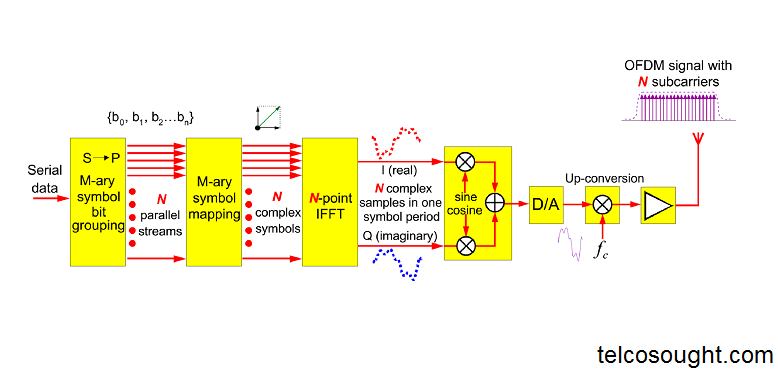
The OFDM Transmitter
This diagram shows a block diagram of the transmitter, which combines the elements of symbol mapping and QAM with the application of IFFT to produce an OFDM signal.
First, the serial data that will be carried over the radio link must go through a serial to the parallel conversion process. The number of data-carrying Subcarriers in the system will determine the number of parallel streams. Because the IFFT offers the best efficiency, this number will almost always be a power to two.
The OFDM Receiver
The OFDM signal is then down-converted and sampled for analog/digital conversion. To include the cyclic prefix, the sampling rate will be factored in at this point.
The cyclic prefix of the sampled signal has been removed and it is divided into I and Q components. This results in a series of complex samples that can be used as inputs to the FFT.
FFT is a method of reducing the complex waveforms in the symbol period to N complex value. Each represents a modulation symbol on one subcarrier. To recover the bits that are represented by each M-ary modulation symbol, M-ary demodulation is done by reverse symbol mapping and integration.
Cyclic Prefix In OFDM
As long as the cyclic period of the prefix is not longer than the maximum delay spread, the effect of ISI can be eliminated or mask by it. To create the cyclic prefix, you take a portion from each OFDM symbol that is ‘usable’ and then copy it onto the symbol period’s beginning. The diagram shows that the total OFDM symbol time (Ts), is the sum of Td (the useful symbol period) and Tg (the cyclic prefix).
OFDM Subcarrier Assignment
Different functions are assigned to subcarriers drawn from the entire OFDM channel’s population. Many subcarriers will carry modulated user information signals. Each subcarrier will carry only one part of the parallel signal being transmitted over the multi-tone channel. Each data subcarrier’s data rate is determined by the combination of the modulation scheme used and the symbol rate.
Some OFDM variants, such as the WiMAX version, allow entire subcarriers to carry ‘pilot signals’. Pilot subcarriers are used to make channel quality and signal strength estimations and to allow for other control functions such as frequency calibration. Pilots transmit at a higher power level than data subcarriers, typically 2.5 dB more. This allows them to be easily acquired by receiving stations.
Scalability in OFDM
If the subcarriers’ number remains constant, however, that the speed of the total OFDM channel increases and the separation between subcarriers will grow in relation. The increased subcarrier separation implies that the symbol rate of each subcarrier will increase in proportion. Otherwise, any orthogonality that exists between the subcarriers would disappear.
The diagram on the top illustrates a subcarrier set that operates orthogonally.
The center diagram illustrates an example of how it is clear that the OFDM channel’s bandwidth increased, as well as the FFT size and subcarrier symbol rates, are maintained. The spacing of subcarriers has increased because of this, and it is evident that the subcarriers ‘ positions are no anymore orthogonal.
Scalable OFDM
It’s been discovered that the most efficient method for working in different bandwidths is to change the size of FFT rather than using the symbol rates of subcarriers. This means that many of the important system parameters are the same for various bandwidths, which gives more chances to take advantage of channel adaption when the channel’s overall bandwidth is greater.
This method is commonly described as an OFDM that is scalable. The figure illustrates the operation of the 5 MHz frequency range that has an FFT of size 512, and it is the same system operating in a 10- millisecond channel, with the FFT of size 1024. The symbol rate and the subcarrier separation requirement is the same in both scenarios and orthogonality is preserved.
OFDMA Resource Allocation Strategies
The most straightforward way to get multiple access within the OFDM device is to employ an aspect of time-multiplexing that is incorporated into the OFDM radio bearer. This is clearly illustrated in the upper portion in the figure. Each user gets the full bandwidth of the channel as well as each data subcarrier is exclusively used for a specific number of symbol intervals.
The highest efficiency is possible when an adaptive time-allocation system is used in a way that users who have greater bit rate requirements are assigned a higher percentage of their time. However, in this system, the most resource allocation is just one OFDM symbol. Even using dynamic time allocation, this arrangement could be inefficient if there is a high need for several lower bit-rate connections, such as when several voice circuits are in use.
Take the case of an OFDM system running at 10 MHz bandwidth with an FFT with 512 points and 16QAM. In the absence of reference and null subcarriers, a system could be able to transfer on 1600 bits within a single OFDM symbol time. This might seem like a tiny resource, but the delay requirements should also be considered. In a real-time application like voice, it is important to limit round-trip delay.
To satisfy the requirement for delay for a voice-based service, resources will be allocated, for instance at least once every 20 milliseconds. This could mean the case of a minimum bandwidth allocation for one user at a rate of at least 80kbit/s (or 120 kbit/s when 64QAM is being used). While allowing for errors protection overhead, this resource could significantly decrease the efficiency of the system and its capacity to gain the benefits of advanced techniques such as discontinuous transmission or channel adaption.
Subchannelization Organization
Subchannelization in practice is typically achieved through the systematic division of all subcarriers available into a group of channels. The smaller the set of subcarriers that are part of each channel, the more precise the resource allocation.
In some systems, the subchannel definition could be fixed, and the allocation of resources will be based on the determination of the subchannels to some or all symbol times. However, the system’s performance could be improved if the subchannel structure is changed to make it more adjustable.
The most significant feature of subchannel structure is the method the subcarriers grouped together are allocated within the bandwidth of the channel. There are two main options that can be used: they could be distributed or localized.
Channel Adaptation
The quality of radio links is affected by a variety of factors, such as interference, fading as well as time dispersion. Radio channels from terrestrial mobile that are typically thought to be non-line-of-site are often very weak. This is why the majority of terrestrial cellular radio systems are built with robust modulation strategies as well as large overheads to protect against errors.
But a closer examination of real-world conditions on the channel will reveal that they are highly different in very small time intervals, and most of the time, every channel will exhibit excellent performance. Therefore, the most common approach is to engineer the channel to tackle the most extreme case, which is only a tiny period of time.
OFDMA Allocation to Users
Within an OFDMA system, subcarriers in groups are allocated to multiple devices from the total channel bandwidth. So, multiple users are served at any one moment. In a system for scheduling that is fast, this assignment can change quickly. In addition, at any moment, a variety of subcarriers are in use as references. The positions of these reference signals can change over time.
The diagram illustrates an instance that a localized allocation subcarrier is used to create users’ subchannels. It is also possible for the subcarrier’s allocation by a user to be distributed across the channel’s total bandwidth in addition to the pattern of distribution to shift on a symbol-by-symbol basis.
When channel adaptation is employed, different transmit powers, modulation schemes, and error protection overheads will be determined for each resource allocated as appropriate to the needs of the service along with the radio channel’s conditions.
Turbo Coding for Error Correction
Enhancing the effectiveness of error protection strategies are a key element of any system that aims to offer broadband radio services. To be able to handle the significant volume of higher-data-rate traffic, it is essential to discover ways to improve the efficiency of spectral.
A more robust error prevention system can be utilized to decrease the signal-to-noise percentage at receiver. This means that a higher amount of interference could be accepted, which results in an increase in capacity. But, this should be done without an increase in the error protection overhead, since an increase in the error protection overhead could eat up the gain in capacity.
Turbo Decoding
The exact procedure of the Turbo decoding algorithm is very complex, however the principle of operation is explained by the figure. The Turbo algorithm is an iterative method which relies on confidence information for each repetition. Each subsequent iteration is based on a constitutive coder 1 or 2 decode. The output of each decode will provide information on the reliability of the next decode.
This procedure is repeated until there is a minimal improvement in the accuracy of the decode over repeated iterations, which is typically between 18 and 20 times. Utilizing this method will result in significant improvements in error correction efficiency as compared to a simple convolutional coder. However the decode algorithms are more complex , and multiple iterations need to be executed very quickly in order in order to avoid accumulation delay. In addition, the improvement in performance is noticeable when large blocks of data are used.
What is Peak-To-Average Power Ratio: OFDM
It is the OFDM signal is made up of multiple sinusoids with different frequencies and carrying various modulation symbols. The sum of these sinusoids creates a complex waveform that has a much higher peak-to-average ratio than one single carrier signal could have.
Since diverse types of transmission symbols happen on the multiple subcarriers simultaneously the combined transmitted signal displays the regular appearance of an extremely higher level of PAPR (Peak to Average Power Ratio). The greater the number of subcarriers, the more frequently this happens. This means that in order to keep the linear operation within the power amplifier, a greater power backup-off has to be in place. This can mean lower efficiency or costlier power amplifiers.
SC-FDMA Principles of Operation. ( sc-fdma block diagram )
sc-fdma block diagram The layout typical of an SC-FDMA receiver is illustrated in the diagram. In spite of its name, the radio signals for the SC-FDMA are orthogonal multiple carrier signals like OFDMA. The term “single carrier” is a reference to the preprocessing of the baseband information prior to its transfer to the IFFT.
Data streams are delivered in a series in the process of radio transmission. The first step is the modulation symbol mapping that produces multiple blocks of “M” complicated valued symbols. The amount of bits that are represented by each of the modulation symbols is determined by the modulation scheme used.
Multiple-In Multiple-Out ( MIMO ) system
The method involves placing a number of uncorrelated antennas at the transmitting and receiving sides of the link. In the event that there is four antennas that are uncorrelated at the transmitter and additional four uncorrelated antennas on the receiver there are 16 direct radio paths that connect the receiver and the transmitter. Each one of them is susceptible to multipath effects, resulting in further radio pathways between the transmitter as well as receiver. These radio paths could be combined constructively, creating micro diversity gains in the receiver.
Since the receiver is able to differentiate among the different uncorrelated antennas It is possible to transmit various streams of data along different routes. The stream of data that is transmitted to each antenna could be described as a “layer and the number of antennas that are available in the receiver and transmitter can be described as rank. For instance, the system that operates with an array of 4×4 MIMO antenna array could be described as with four layers, and being of rank 4.
The Benefits of MIMO:- Advantages of MIMO
MIMO can be a complex technology, but it could provide huge benefits to systems capabilities. There are three primary ways that MIMO can improve the efficiency of systems. Any MIMO implementation could reap the benefits of these advantages or be set up to make use of only one or more of them. Ideally, a system must be designed with enough flexibility in MIMO implementation to permit the system administrator to select the best method for different conditions or system objectives.
The gain in diversity is derived from the use of multiple antennas at either the receiving and/or transmitting ends of the link radio. This leads to multiple transmission paths that have decor-related fade characteristics. This results in an improvement overall in the channel signal-to-noise ratio, which results in increased capacity and reliability of the channel.
What is MU-MIMO ( Multi-User MIMO )
The most basic application of MIMO is often known as the SU-MIMO (Single-User MIMO).
The SU-MIMO idea can be expanded to include the MU-MIMO (Multi-User MIMO). In this case, the spatial multiplexing capabilities of MIMO have been utilized to multi-patch the link to multiple mobiles by using the same frequency and time resource. The order of the multiplexing available depends on the number of antennas (or rank) that are available at the end of the transmitter and receiver on the connection. For instance, the figure illustrates a 2×2 MIMO arrangement used for MIMO using two mobiles.