5G Cloud RAN Fronthaul Architectures
Introduction
The Cloud-RAN is consists of RRH and BBU in 4G and RRH, DU, and CU in 5G, where BBU, DU and CU can be hosted on shared Cloud Infrastructure. RAN Cloudification is enabled by RAN split architecture i.e. The BBU/CU/DU can be hosted on centralized servers while the RRH remains on the Cell towers. The RRH is connected with the BBU/CU/DU units using a digital interface names as CPRI/eCPRI for transmitting radio signals.
5G Cloud RAN Fronthaul Architectures.
Why Cloud-RAN?
- Using BBU/CU/DU on cloud enables effective utilization of resource with resource pooling, which allows for greater network scalability and bring down CAPEX
- Cloud RAN architectures allow for BBU/CU/DU virtualization on public and private cloud
- RAN maintenance is simpler with a significantly lower number of centralized aggregation sites as compared to large numbers of cell sites bring down the OPEX
- It decreases power consumption at cell sites
- It reduces facility leasing expenses at cell sites
- It allows for more sites for RRH deployment
CLoud-RAN Fronthaul Architecture
In Cloud RAN architecture, the fronthaul transport network connects the RRH from the cell site with the BBU/DU/CU in a central location in the Cloud data center. When C-RAN is deployed in dense urban locations and fronthaul transport network provides additional ethernet services to business and residential customers collocated in buildings with cell sites along with connectivity between RRH and BBU/DU/CU.
Therefore, the fronthaul network can serve the following two purposes:
- Connectivity between RRH radios and centralized BBU/CU/DU
- Ethernet connectivity for business or residential CPE devices
Fronthaul Network Architecture Choices
There are following ways to build fronthaul transport networks
- IP Fronthaul Network
- Optical FH network with ROADM
- Optical FH network with active P2P DWDM
- Optical FH network with passive P2P DWDM
IP Fronthaul Network
The IP FH network is shown in following figure, uses IP/MPLS transport end to end. The IP routers are specially designed for fronthaul with CPRI and eCPRI digital interfaces to connect RRH with BBU/CU/DU signal processing units. Here IP routers are located at cell sites connects RRH and CPEs devices providing business services. Cell site FH routers are connected to central BBU/CU/DU locations using 100GE links over fiber.
![]()
IP Fronthaul have following benefits:
-
- Allows for end-to-end management, control and provides multi-service transport
- Supports legacy backhaul for 2G, 3G and 4G radios
- Enables flexible topologies: ring, PT-PT, tree and Offers full monitoring and control of Layers 1−4
- Leverages automation and orchestration
- IP routers have a lower TCO than other active solutions
- Disadvantage
- As this is New architecture for fronthaul so requires lots of testing enable all scenarios
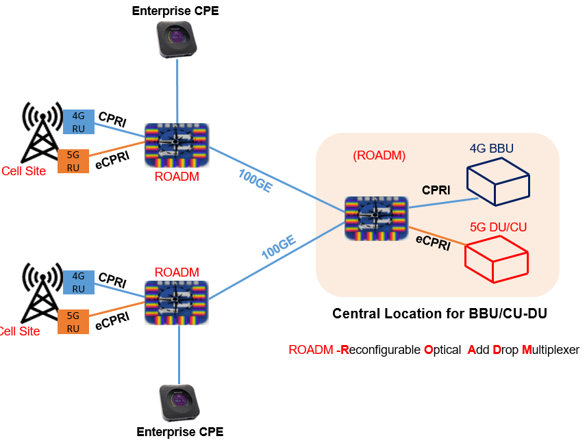
Optical FH network with ROADM
FH network with ROADM is shown in following figure. ROADM is a Reconfigurable Optical Add Drop Multiplexer is a form of optical multiplexer that adds the ability to remotely switch traffic from a wavelength-division multiplexing system at the wavelength layer. The ROADMs have transponders with CPRI and eCPRI interfaces to RRH. Business CPE can also be connected to the ROADM via Ethernet interfaces. The ROADMs provide high-capacity optical transport of CPRI and Ethernet traffic to the central sites. RRH connect with BBU/CU/DU units over DWDM.
- Advantages
- High Capacity optical network
- Flexible topologies allows i.e. Ring, P2P, Tree
- Allows monitoring and control at Layer 1
- Disdavantes
- Highest cost Layer 1 network, no visibility into Layers 2−4
- Complex network management and design
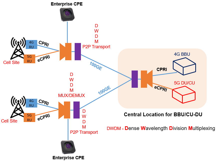
Optical FH network with active P2P DWDM
ROADMs optical networks are flexible and scalable but also very expensive can shoot up CAPEX. A less expensive solution can an active P2P DWDM network, shown in following figure. This architecture only allows for P2P connections between the cell sites and central Cloud-RAN. It allows for both monitoring and optical amplification, if required. In this architecture, the RRH, CPE devices, and BBU/CU/DU units use DWDM colored pluggable optics at different wavelengths. The signals are multiplexed and de-multiplexed by passive DWDM MUX/DEMUX units and transmitted by active DWDM P2P transport systems.
- Advantages
- Simple and High capacity Solution
- Allows Monitoring, Operations and Maintaince at the optical layer
- Disadvantages
- Limited to P2P topology
- Layer 1 network, no visibility into Layers 2−4
- Higher CAPEX than router solution with significantly less functionality
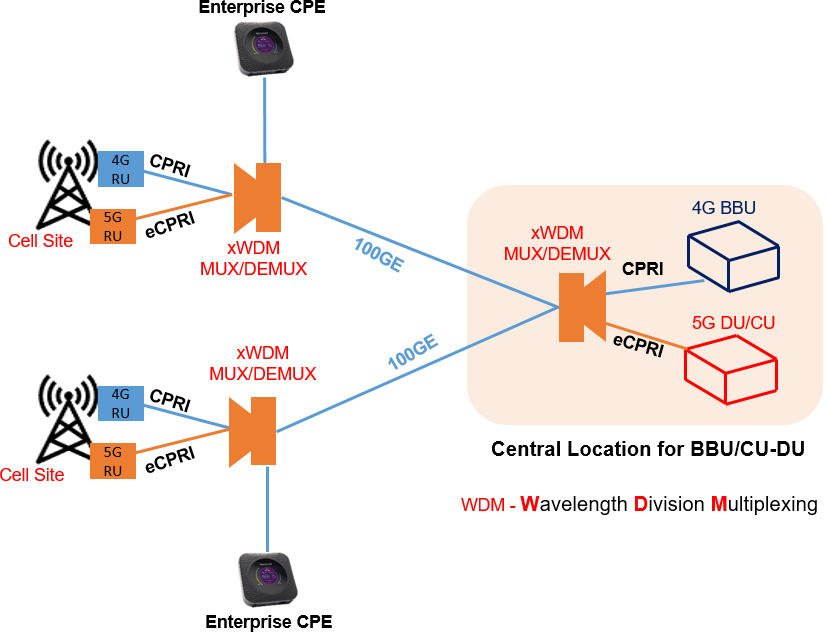
Optical FH network with passive P2P DWDM
A further cost effective solution can be with optical connectivity using passive DWDM network represented as shown in figure. This solution is like the previous architecture without the active P2P DWDM transport nodes. Cloud RAN have strict latency and distance requirements between the RRH and the BBU/CU/DU and usually do not requires amplification.
Passive optical network does not support monitoring of the optical signal. In both the active and passive architectures pluggable colored DWDM optics are used at all the end points.
- Advantage
- Simple and High Capacity Solutions
- Low cost
- Didavantage
- Low capacity with Limited to PT-PT topology
- Layer 1 network, no visibility into Layers 2−4
- No Operation and Management
Reference
- White Paper on Fronthaul Architectures for 5G
Related Posts
Also, you can Read- 5G Handovers – Connected Mode Mobility.