

In 4G LTE, to achieve link adaptation in the downlink (DL) the UE reports downlink channel quality to the eNB and then eNB select the most approriate MCS. The downlink channel quality is a set of 16 possible CQI values starting from 0 to 15 and the MCS is a set of 28 different formats.
Once eNB selects a particular MCS, it is signaled by a 5 bits field known as called IMCS in the PDCCH (DCI) preceding the PDSCH subframe that carry the downlink data. The procedure is similar for uplink; where only difference is that the eNB measures the uplink channel quality based on SRS sent from the UE and then command appropriate MCS.
Channel Coding for PDSCH
Following figure show the LTE channel encoding procedure from Turbo encoding. A Transport Block (TB) is initially appended with a CRC and process further. Turbo encoder admitts blocks of bits with specific sizes and maximum size it can take is about 6144 bits. If the Transport block is bigger the 6144 bits then it can be fragmented to obtain one or multiple code block smaller or equal to 6144 bits. If Transport Blocks are fragmented then each resultant code block is again appended with an additional CRC.
![]()

Based on fundamentals of Turbo Code rate 1/3 which generates output as three flows of bits: systematic, redundancy 1 (R#1) and redundancy 2 (R#2).
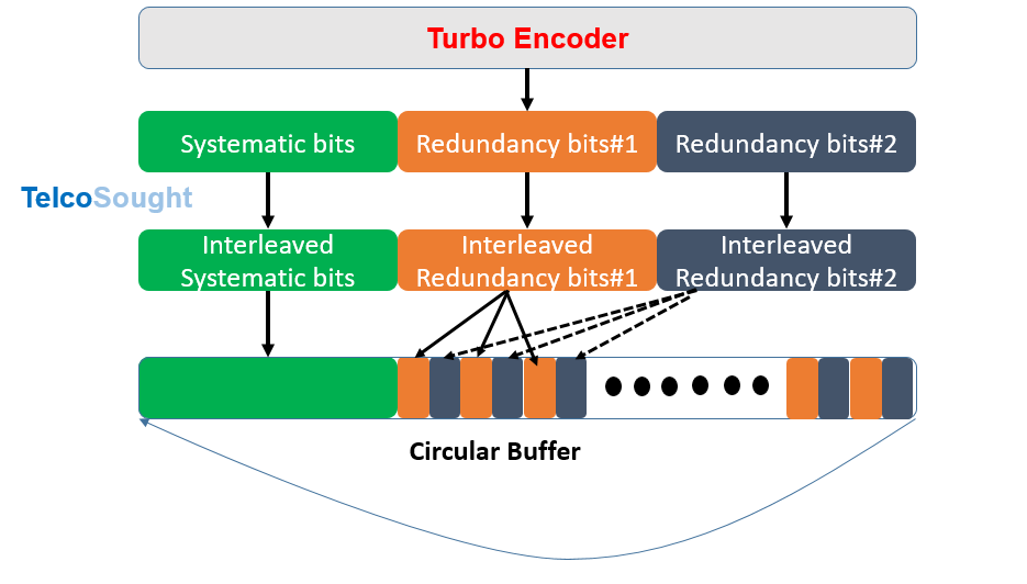

The procedure to select which coded bits will be transmitted at the next subframe is called rate matching. The desired coding rate is adjusted by varying the number of punctured (or repeated) coded bits. This procedure is based on a circular buffer where coded bits are written after being conveniently interleaved. The systematic bits are written first and are followed by the redundant bits. As code rate is 1/3, if the size of code block to be transmitted is N bits, the size of the circular buffer is n = 3N+12, where 12 bits are used for trellis finalization.
RV Version for HARQ
After apply the 1/3 code rates the code block form a codeword and codeword bits are filled into A circular Buffer. The Buffer is divided in up to 4 different sectors and 4 rv’s are obtained by reading different sectors of the circular buffer. The depicted situation corresponds to a high code rate (near unity).
- The first rv (rv = 0) includes almost only systematic bits
- rv’s from 1 to 3 are formed by reading subsequent portions of the circular buffer which includes interleaved redundant bits

Point to be noted here that each of the rv’s is decodable by itself and each rv partially overlaps with the previous one. The size of the four possible rv’s is the same, and it is this size what determines the code rate, since for rate 1/3 (for example) each rv would encompass the full circular buffer, while for rate < 1/3 each rv encompasses more than one turn of the circular buffer. So for rate < 1/3 there are at least some coded bits that are transmitted more than once within the same rv, and in general we can say that, after rv = 3 has been received, some coded bits may have been transmitted only once while others may have been transmitted more than once.
Why rv’s decoding is done as 0,2,3 1?
The reason for rv=2 after rv=0 is because it has no or minimu overlap with Systematic bits and have more redundant bits, so there are more chance of data decoding. We can take following example to understand the overlaping of different rv’s.
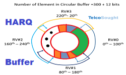
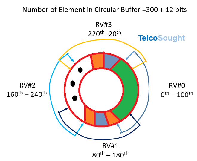
- For example lets consider a HARQ buffer of 300 elememnts
- Lets assume RV#0 starts from 0th and ends at 100th
- RV#1 starts at 80 and ends at 180
- RV#2 starts at 160 and ends at 240
- RV#3 starts at 220 and ends at 20
If we transmits rv=1 when rv=0 decoding is failed, then the circular buffer will read 80-180 i.e. 0-180 with (80-100 transmission twice) and less chances of HARQ data recovery and less number of redundant bit (only 80 bits are redundant and 20 bits are duplicated due to twice transmission).
if we send rv=0 and rv=2, we transmit 0-100 and 160-240, there are more redundant bits (all 100 bits) transmission here and more probability of getting decoded due to systematic and R#1, and R#2 all available.
References:
- 3GPP TS36.212 E-UTRA; Multiplexing and Channel Coding
Related Posts: